¶ Apreo SEM
| Location | Ultramicroscopy Hall (GW0.016) |
|---|---|
| Functions | SEM, EDX, GIS, nanomanipulator |
| Specimen | About 20 samples that fit on a 12mm diam. stub, beware that if you would like to image high samples, that you should discuss it with the responsible technician. |
| Manufacturer | ThermoFisher |
| Useful files |
- SEM manual - Paper 'Trinity detectors' - Periodic table for EDX |
| Responsible | Luc Wigbout |
The ThermoFisher Apreo SEM is a Scanning Electron Microscope with a standard Everhart Thornley Detector (ETD) and three in-column "Trinity" detectors. The Apreo SEM has some additional detectors, enabling several other probing techniques in-situ, e.g. energy dispersive x-ray spectroscopy (EDX) to quantitatively measure spectra and qualitatively create spectral maps at the micro- and nanoscale.
Large (tall) samples should be discussed first with the responsible technician!
¶ Manual
If the Sample Exchange window is not showing, press the
-button in the upper-left.
If the live CCD image is not showing, first close the Sample Exchange window, and check the lower-right window of the quad-view. Make sure that the right detector-type is selected. There should be a light-bulb in the lower-left corner.
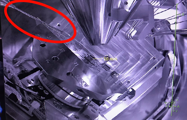
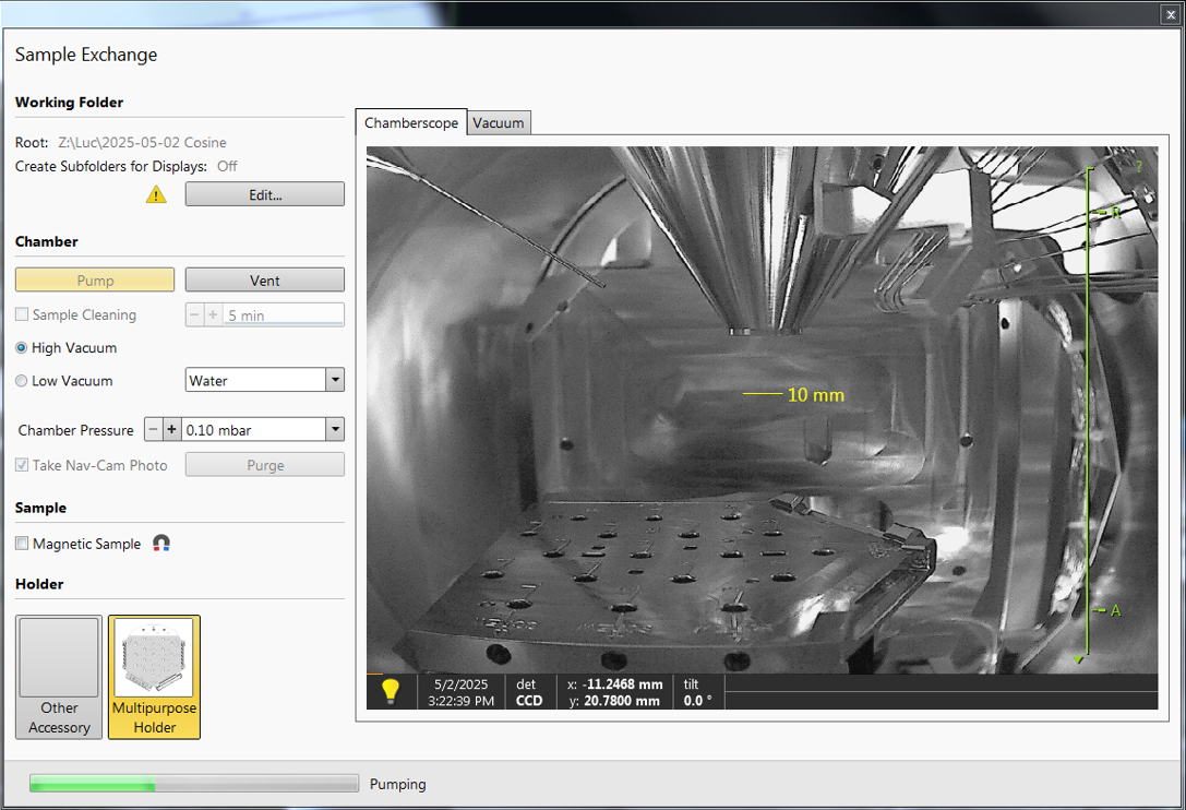
When you walk in, you should see the Sample Exchange window, which should look something like the figure on the right. The grayscale image is a live CCD image of the chamber, where you can see the stage at the bottom, the conical objective at the top, and the GIS needles at an angle.
The screen on the left should have an Excel sheet open, with the logs from previous users. Check if there are any comments from previous users that are important to keep in mind during your session!
Before venting the system, check the chamber pressure on the right screen in the bottom left. The previous user should have pumped the chamber to high vacuum again, so it should be <1e-5 mbar. Write the pressure in the logbook! Furthermore, write down the emission current and the electron source pressure!
If not done already, mount your sample on a SEM-stub, using either carbon- or coppertape, or carbonpaint.
Open the chamber while looking at the live CCD image, to make sure you do not touch the objective lens.
Load your sample onto the stage. Of course, you do this while wearing orange (powder-free) gloves! When closing the door, make sure that your sample does not touch (and thus damage) the objective lens!
In the Sample Exchange window, make sure that 'High Vacuum' is selected.
Make sure to check the box 'Take Nav-Cam Photo', so that the stage will automatically move into the Nav-Cam position and take an image.
If you have a magnetic sample: check the box of 'Magnetic Sample'.
Pump the chamber, choose 'no accessory'.
While the chamber is pumping, you want to change the subfolder to D:\User\<yourname> on the Support-PC. and close the Sample Exchange window.
¶ Setting up
Check if the settings are in default:
- It is in Standard Mode

- The detector windows (top two windows in the quad-view) have the detector icon

- Magnification is 100x (or lower)
- Set the voltage and current to your desired values (default: 15 kV, 0.10nA, insulators: 2kV, 13pA).
Check for the top two quad-view windows:
- The detector should have the right settings (if not, right-click on the text and change it):

- The ETD should be selected initially.
- The ETD has most contrast in SE (Secondary Electron) mode, but will also function in BSE (backscattered electron) mode, especially if you want to see contrast between elements!
Check additional settings:
-
Set the dwell time to 100 ns, this is recommended during imaging, as the refresh rate will be quick enough to see the effects of turning the knobs (focus, stigmator, etc.) quickly.
-
Set the resolution to 3072x2048 or smaller. Typically, high resolutions are not necessary during imaging and make the refresh rate unnecessarily slow. Taking HQ micrographs, however, is useful sometimes.
If the chamber pressure < 9.9e-5 mbar you can turn the beam on in the Beam Window.
On the Nav-cam, double-click the highest sample and hold your hand above the ESC-button.
Everytime you move the stage, you should hold your hand above the ESC-button so that you can abort movement immediately when the stage touches anything!
Obtain a clear image of the sample: zoom -> focus -> zoom -> focus -> etc.
Get a good focus at >20 000x magnification, so that the calculated Working Distance (WD) has a small error. (While rotating the focus knob, notice that the WD in the blue bar of the quad-view changes.)
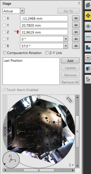
Open the Stage window, and notice the red arrow pointing up, denoting that the stage is not linked. Also notice the Z-height. This is defined from the bottom of the chamber to the top.
Press 'Link Z to FWD'-button ![]() , which then changes to
, which then changes to ![]() .
.
Again, look in the Stage window, and notice how the arrow is switched to a white arrow pointing down ![]() . Also notice that the Z-height changed its value, as the Z-axis is now defined from the objective lens downward!
. Also notice that the Z-height changed its value, as the Z-axis is now defined from the objective lens downward!
In the Stage window, move the Stage to Z = 10 mm. This will leave 10 mm between the objective lens and the sample, i.e. bring the sample up toward the yellow line you see in the live CCD image.
At Z = 10 mm, refocus on your sample.
Relink the FWD, and move again to 10 mm. Now the working distance should equal the Z-distance.
Gather data!
When you're done, make sure to leave the Apreo behind properly.
¶ Cleaning up
Your session is coming to an end. 15 minutes in advance, you will have to close down by following these steps:
- Lower the stage to Z = 20 mm.
- Turn the beam off and write in the logbook.
- Set the usecase (back) to Standard Mode .
- Select the ETD and set parameters (voltage, current, dwell time, resolution, magnification) back to normal
- Vent the system and retrieve your sample.
- With the empty chamber, pump again (no accessory) and wait until the pressure is <9.9e-5 mbar before you leave!
- In the meantime, you can copy your files from
D:\User\<yourname>on the Support-PC to a USB stick or to\\data03.physics.leidenuniv.nl\microscope\<yourname>if necessary.
No USB-sticks are allowed in the Microscope PC (the PC on the right)!
- Clean up your mess, also on the sample preparation table! If the yellow bag is full, dispose of it. If the gloves are empty, either get some gloves at the FMD Magazijn.
¶ Tips during imaging
This section describes some useful tools during imaging. To speed up your workflow, you could check out the Keyboard Shortcuts in the manual or click on the image on the right.
¶ A scanning beam
Remember SEM stands for scanning electron microscope, this means that the electron beam is scanning across your sample at high speeds due to a potential change in the x- and y-deflectors.
On the left of the quad-view image, you see an orange line which shows you where on the slow-axis (vertical scanning) it is scanning.
Since the fast-axis (horizontal scanning) is so quick, there is nothing that depicts that axis.
So, the beam is scanning across your sample and the detector is simply measuring the amount of electrons 'reflected' from that part of the surface.
The detector measurement and the x/y-deflection of the beam are phase-locked, such that the image is generated.
Remember that there is no live image with this technique.
¶ Contrast and Brightness
In order to properly focus on your sample, it is useful to have a feature in your image with some contrast.
To get some contrasting features, change the contrast and the brightness; these act as gain and offset respectively.
These gain and offset are actual physical parameters (voltages) that you change in the detector; these are not the digital after-the-fact changes to the image alone!
- Open the Videoscope (F3)
- Change the brightness knob and set the darkest regions to be black (pixel value 0).
- Change the contrast knob such that the brightest regions are white (pixel value 255 for 8 bits, 65535 for 16 bits). This way, you use the complete resolution of pixel values.
¶ Focusing
After you actually get an image with some information, you are ready to focus onto a small region of your sample.
- Zoom with the large magnification knob. Remember that this only changes the electromagnetic lenses, and does nothing to the stage height; therefore, you can increase this rapidly (contrary to optical microscopy).
- Focus using the coarse knob first, and using the fine knob after.
- Afterwards, you can zoom again to enhance your focus! This way, you can see if you were actually in focus, or that the blurriness (defocus) was simply smaller than the imaging resolution of your image. Remember the mantra: Zoom to focus!
¶ Stigmators
At some point, focusing will come to a halt, as you will see that only parts of your sample will be in focus, while other parts are not.
In order to continue, try to obtain a focus such that all parts are 'equally blurry', i.e. 'equally in focus'; this is called the plane of least confusion.
It is easiest to find this plane using features that have some contrast in X- and in Y- direction, as to check the blurriness of that contrasting part.
IMAGE IMAGE IMAGE IMAGE IMAGE IMAGE
- Try to wobble the focus, i.e. turn the knob back and forth and try to find the point in between the stigmated images.
- After finding the plane of least confusion, optimize the focus by changing the X stigmation by rotating the knob. If it doesn't get any better than you previously had, that is okay too.
- Optimize with the Y stigmator knob now, maybe optimize the X stigmator once more.
- Your focus should have improved.
If the stigmator is not working as you think, it might be useful to check in the Beam Settings Window if the small stigmator square is somewhere around the middle.
If the stigmator is (still) not working as you think, check if you are actually in the plane of least confusion, you probably aren't.
If the sample is shifting in X- and Y-direction during the rotation of the stigmator knobs, you might want to check out the stigmator alignment under the Direct Adjustments tab.
¶ Stage Coordinates vs. X/Y Shift
XYZ and R,T.
Stage > Align Feature
¶ Frame time
SNR increases in time and electron counts.
Resolution / Dwell Time / Reduced Area
¶ Minimum settings while imaging
¶ Minimum settings for photos
20us no integration
However: driftless settings 1 us, 20x integration and drift correction
¶ Trinity Detectors and Use-Cases
White paper
¶ Alignments
Lens alignments
Cross section
¶ More..?
More tips and tricks will come... If you have any tips, we encourage you to contribute to the NanoWiki!