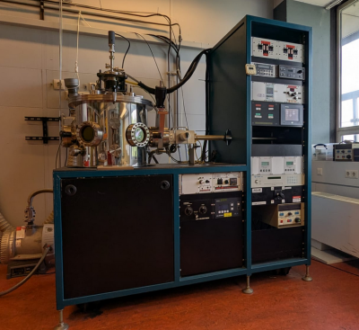
¶ AJA International ATC 1800F
| Location | Sputtering Lab (HL603) |
|---|---|
| Functions | RF or DC (reactive) magnetron sputtering system |
| Specimen | Several ~ 15x15 mm samples, standard wafer thickness |
| Manufacturer | AJA International |
| Useful files | - ATC Manual - Bos, Thoen, et. al. - Berg, Nyberg model |
| Responsible | Sander van Leeuwen Luc Wigbout |
The ATC-1800 sputtering system is feature-rich four-magnetron system with a large deposition pressure range, 10-8 mbar range background pressure, substrate heating, substrate RF bias, variable sputtering distance, planetary substrate rotation and multi-channel gas blending (inert Ar and reactive O2 and N2). The gas inlets are connected to both the chamber (reactive gases) and the sources (inert gas). The system has a loadlock for high throughput and a vacuum chamber that is easily accessible for non-standard work.
There is a plethora of materials available. For reactive sputtering this is Nb ( NbNx), NbTi ( NbTiNx), Zr ( ZrNx) and Ru ( RuOx). Additionally, there is NiFe, Co, Al2O3, Al, Cr, Py, Cu, Mo, Fe, Ag, Ni, Nd, W.
¶ Manual
Check if the gate valve between the chamber and the loadlock is closed before venting the loadlock.
Vent loadlock by switching off the loadlock pump group - not the main power!
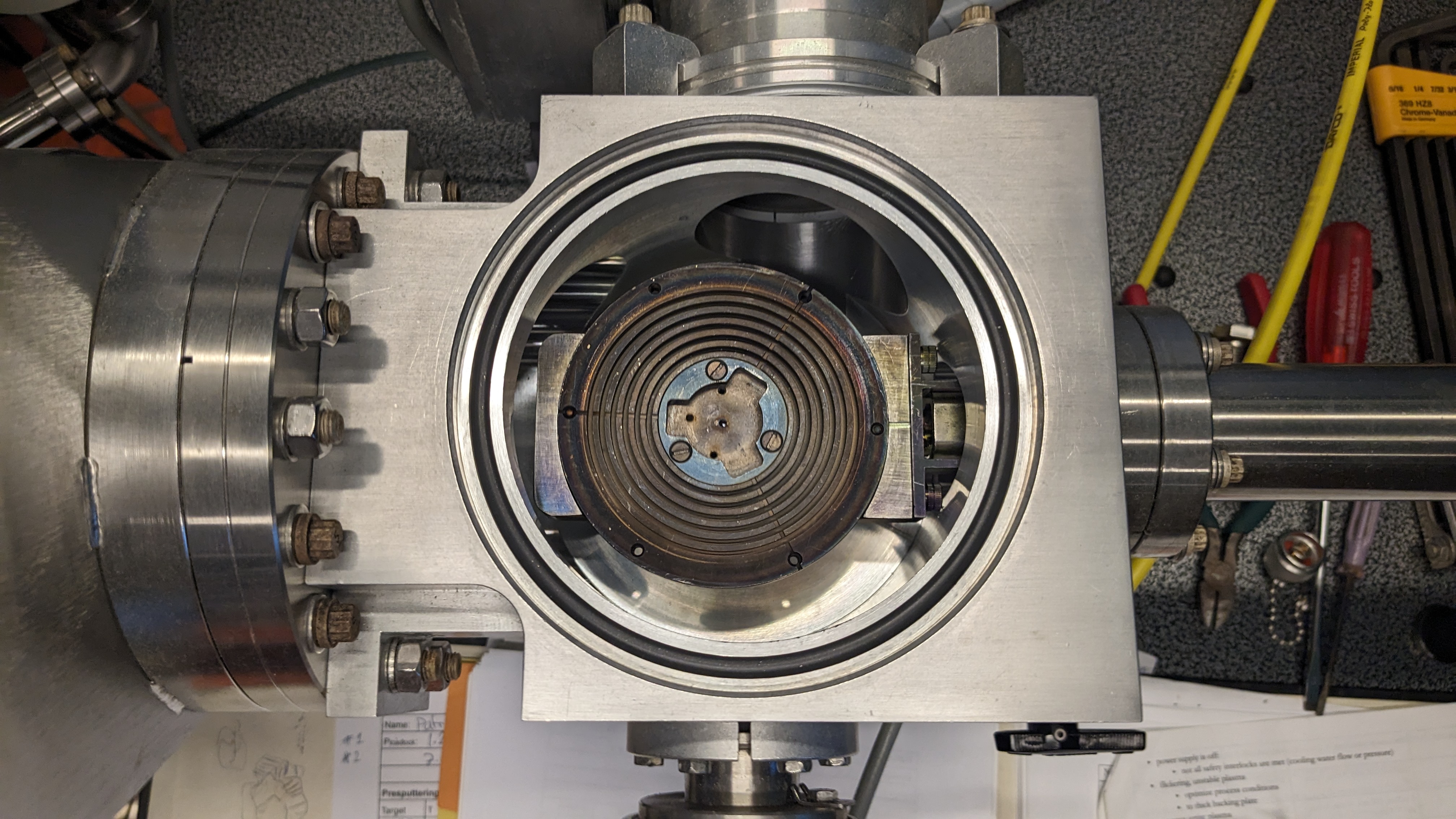
Mount the substrates on the sample holder with silverpaint (leave paint to dry for at least 5 minutes) or clamp the sample with a compression spring-like mechanism. Put the sample holder in the loadlock with the two screws in the elongated holes, and the three alignment slits at the edge of the holder such that one is pointing towards the right viewport (see image). Put the lid on the loadlock, making sure that the rubber o-ring is clean, switch on the loadlock pumpgroup to pump it down, and wait until the pressure is below 10-6 mbar.
While pumping down, you might want to open the valves of the gas inlets in the main chamber via the touch screen after making sure that the potentiometers of the mass flow controllers (MFCs) are set to zero. Even though they are set to zero, this will create a short pressure surge because the MFCs are a bit leaky and some residual gas might have built up between the MFCs and the valves. By opening the valves at this stage, you make sure that this gas surge does not happen when your sample is inside, which would mean that you have to wait a bit more in order for the chamber to pump down to the pressure before the surge.
Additionally, at this point you can put a lamp at the left viewport of the main chamber such that you can see the sample holder stage.
Write down the loadlock pressure in the logbook before transferring the sample into the main chamber! Open the gate valve between the loadlock and the main chamber.
Slowly insert the sample holder with the transfer arm, and check that you don't crash into the sample holder stage. If you think the arm will crash, you can heighten the stage and put the sample holder underneath: the transfer arm should be inserted fully.
You should be able to see the alignment slits at the edge of the sample holder through the viewport with the help of the lamp. Make sure to align the propellors of the stage with the alignment slits. Once the slits are aligned, carefully lower the stage until it touches the sample holder: be very careful not to bend the transfer arm while doing this. Grab the sample holder by rotating the propellors clockwise (CW) manually. Do not force anything!
Pull the sample stage up about 1 cm using the joystick - make sure that the lowest point of the screws at the bottom of the sample holder are above the highest point of the transfer arm - and turn on the rotation to see if it's levelled (8.0 V is approximately 27 rpm.). Once it is levelled, raise the sample stage further and remove the transfer arm from the chamber and close the gate valve.
Set the sample stage to the desired working distance.
If rotation speed > 40 rpm you run a higher risk of dropping the sample holder during heating!
Set the substrate temperature to the desired value, let the heater bake until the desired pressure/Temperature is reached.
Set the switchbox to the desired gun.
Open the gases you need on the touch screen, if not done already.
Set the gasflows with the MFCs.
Switch the VAT-valve to pressure mode (typical setpoint is 5mTorr).
Close shutters of chamber before sputtering.
Set the settings on the power supply (to not go over ~500V/100W)
Press start on power supply to ignite plasma.
Presputter with shutter closed.
If RF/bias is needed, make sure to read the proper manual first, switch off the gun, set the pressure to 25 µbar, ignite the bias, set the pressure to the process value, adjust RF matching and restart the gun
- Open shutter and start timer
- When done, switch off the gun and bias immediately
- Switch off the heater and gases (probably you also want to do this immediately)
- Open VAT-valve fully
- Switch off rotation
- When the sample stage has cooled to below 50°C, transfer your sample to loadlock
¶ Removing the sample
- Move sample stage fully up
- Open gate valve
- Move transfer arm to end stop
- lower sample stage and drop sample holder on transfer arm
- Put sample stage fully up
- move transfer arm to the loadlock
- close gate valve
- Vent the loadlock as described above in order to remove your samples
- Check whether the sample holder is really cold
- Remove the samples from the sample holder, put sample holder back and pump down the loadlock as described above
- Fill out the logbook with all required information.
¶ Leaving the system
¶ Common problems and tips and tricks
- power supply is off:
- not all safety interlocks are met (cooling water flow or pressure)
- flickering, unstable plasma
- optimize process conditions
- to thick backing plate
- cannot ignite plasma
- to thick backing plate
- optimize process conditions
- faulty power supply
- target not conducting
¶ Deposition rates
Source tilt angle, substrate angle and source-substrate distance are process parameters that should be mentioned here!
Current configuration:
| Material | Date | Sample ID | Process parameters | Measured with | Result | Rate |
|---|---|---|
| Fe| 20161222| on Si | 5mTorr, 400mA, 7 min | XRR |41 nm | 5.8nm/min |
| Fe| 20161107| MgO/03 | 5mTorr, 200mA | X-ray + profilometer, 20 min, 10 min | 2 thicknesses: 51, 25nm | 2.52 nm/min|
|Nd|20161019+20|MgO/021,22|5mTorr, 30mA, 25 and 50 min|XRR tough fit, profilometer|25 and 50 nm approx | 1nm/min|
| W | 20161011+12 | MgO/011,012| 5 mTorr, 100mA, 25min, 37.5min | XRR | |1.48nm/min|
Older rates
| Material | Date | Sample ID | Process parameters | Measured with | Result | Rate |
|---|---|
| Co | 20160111 | Co | 5 mTorr, 200 mA, 22 min | X-ray | 70.6 nm | 3.21/min |
| Ag | 20150402 | Ag_cal | 5 mTorr, 100 mA, 5 min | X-ray | 39.0 nm | 7.8 nm/min |
| Co | 20150402 | Co_cal | 5 mTorr, 200 mA, 15min | X-ray | 27.5 nm | 1.83 nm/min |
| Cu | 20150402 | Cu_cal | 5 mTorr, 100 mA, 10 min | X-ray | 31.1 nm | 3.11 nm/min |
| Nb | 20150402 | Nb_cal | 5 mTorr, 300 mA, 10 min | X-ray | 48.0 nm | 4.80 nm/min |
| Ag | 20131104 | Ag10min | 5 mTorr, 100 mA, 10 min, 4 mm tilt | X-ray | 82.8 nm | 8.28 nm/min |
| Co | 20130911 | Co_cal | 5 mTorr, 100 mA, 15 min | X-ray | 11.48 nm | 0.765 nm/min |
| Cr | 20130911 | Cr_cal | 5 mTorr, 100 mA, 15 min | X-ray | 14.79 nm | 0.985 nm/min |
| Cu | 20130911 | Cu_cal | 5 mTorr, 400 mA, 3 min, 4 mm tilt | X-ray | 51.1 nm | 17.03 nm/min |
| Cu | 20131104 | Cu3min | 5 mTorr, 400 mA, 3 min, 4 mm tilt | X-ray | 49.8 nm | 16.6 nm/min |
| Nb | 20131104 | Nb3min | 5 mTorr, 300 mA, 3 min, 4 mm tilt | X-ray | 14.8 nm | 4.93 nm/min |
| Pd | 20131212 | Pd | 5 mTorr, 100 mA, 4 min, 4 mm tilt | X-ray | ? | 4.92 nm/min |
| Py | 20130911 | Py_cal | 5 mTorr, 400 mA, 3 min, 4 mm tilt | X-ray | 21.9 nm | 7.296 nm/min |
| Py | 20130911 | Py_cal_3mT | 3 mTorr, 400 mA, 3 min, 4 mm tilt | X-ray | 24.9 nm | 8.3 nm/min |
| Py | 20131104 | Py3min_holder_a | 3 mTorr, 400 mA, 3 min, 4 mm tilt | X-ray | 26.3 nm | 8.7 nm/min |
| Py | 20131104 | Py3min_holder_b | 3 mTorr, 400 mA, 3 min, 4 mm tilt | X-ray | 26.2 nm | 8.7 nm/min |
| Py | 20131112 | Py1mTorr_holder | 1 mTorr, 350 mA, 3 min, 4 mm tilt | X-ray | 30.4 nm | 10.13 nm/min |
| Py | 20131112 | Py2mTorr_holder | 2 mTorr, 350 mA, 3 min, 4 mm tilt | X-ray | 27.3 nm | 9.1 nm/min |
| Py | 20131112 | Py4mTorr_holder | 4 mTorr, 400 mA, 3 min, 4 mm tilt | X-ray | 22.1 nm | 7.4 nm/min |
| Py | 20131212 | Py3mTorr_holder | 3 mTorr, 400 mA, 3 min, 4 mm tilt | X-ray | 28.7 nm | 8.1 nm/min |
| Py | 20131212 | Py3mTorr | 3 mTorr, 400 mA, 3 min, 4 mm tilt | X-ray | 26.7 nm | 7.6 nm/min |
¶ Recipes
¶ AuFe samples
In AuFe run 200511 AuFe current was kept constant at 100mA and Au current was changed to obtain 6, 4, 3 and 1.5% samples.
Linear approx. of concentration:
Assume for both Au and AuFe 1 nm = n atoms (Fe conc. is low, atoms have similar size), Au rate is rAu and AuFe rate is rAuFe.
The rates at 100mA have been measured by x-ray, they are rAu,100 and rAuFe,100.
Au source: rAu n atoms/min. AuFe source: 0.06 rAuFe n Fe atoms/min + 0.94 rAuFe n Au atoms/min
Fe/Au = Fe (atoms/min) / Au (atoms/min) = 0.06 rAuFe n / (0.94 rAuFe n + rAu n)
AuFe current is kept at 100mA: Fe/Au = 0.06 rAuFe,100 / (0.94 rAuFe,100 + rAu)
rAu = 0.06 rAuFe,100 (Au/Fe)-0.94rAuFe,100
IAu = 100 rAu / rAu,100 mA
¶ Flat Au films on Mica
Substrate
Mica, punched into 8 or 2.5 mm disks, freshly cleaved just before
loading into ATC. Use a Cu holder for the mica, no adhesives
- Pressure: 20 mTorr setpoint, low -7 background
- Ar Flow: 24
- Temperature: 300deg C for deposition.
- Current: 200 mA for 20 minutes, then 2 minutes 45 mA
- Voltage: Around 500 / 380
- O2 flow: 1
- Heating/cooling rate: Heating: Heat up before deposition to 450 to bake out the dirt from chamber, holder & substrate. Radiative cooldown to 300 for deposition. Anneal for 1-2hrs postdeposition at 300. Cooldown radiative by switching off heat.
- RMS roughness (and better roughness data if available): I think a picture says more than 1000 roughness values. Picture: stm image in air, with a lot of vibrations. Image size 740x640 nm. Shows the typical variation of terrace sizes you find on these samples.
Note 1: This recipe has been taken over (mutatis mutandis) from the
attached article by kawasaki et al. Some details on the growth mechanism
and origin of the triangular facets on the surface can be found in
Lussem et aL, applied surface science 249 (2005) 197-202
Note 2: The parameters I used were not systematically optimized. I
happened to stumble over something that worked good enough for me almost
immediately. The low growth rate (high pressure/low current) of the last
step is most probably important. Lower currents could be a thing to try,
higher pressure is probably less useful (?). A higher growth rate for
the first step might be advantageous, too (lower pressure?). Higher
temperature might not be a bad idea, but going over 500 deg C is not
advised, since mica starts to decompose at these temperatures.
Note 3: Film thickness has up to now not been calibrated. SEM imaging of
film grown at room temperature in otherwise same process suggests around
80 nm thickness.
{{:wiki:kawasaki-uchiki_sputter-flat-gold-mica_surf.sci.lett_1997.pdf|}}
¶ Cu on Al2O3
Presputter: Cu 5 min 100 mA, 25 sccm Ar, 5 mTorr, 100% rotation, 90 C (on lamp)
Sputter: Cu 60 min 400 mA, 25 sccm Ar, 5 mTorr, 100% rotation, 90 C (on lamp)
¶ Miscellaneous
- The digital log sheet: {{wiki:atc_logbook.doc}}
- The new digital log sheet: {{:atc_logbook1.pdf|}}
¶ DONTs
- Never make a modification to the system without consulting a technician
- Never transfer a hot sample holder (cold is ~50 °C)
- Never hot-switch the switchbox (switch off power first!)
- Never exceed 50W RF power for substrate bias
- Never transfer a sample without checking that BOTH loadlock and chamber are at vacuum (below 10-6 mbar)
- Never sputter without a sample holder in place
¶ DOs
- write the logbook
- keep an eye on changing voltage to indicate you sputtered through the target
¶ Maintenance
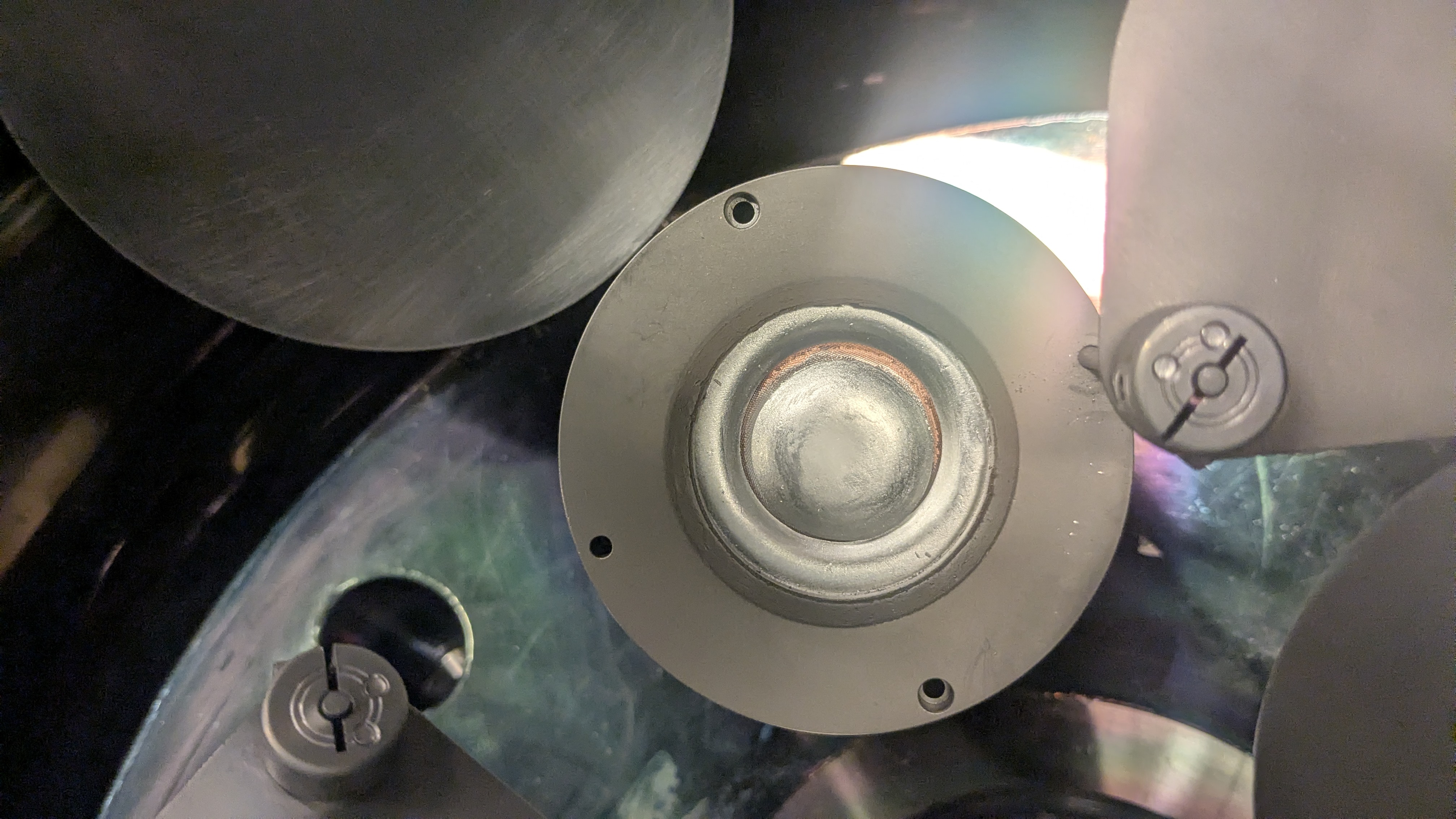
This target needs to be replaced: