¶ Wire bonding
Wire bonds literally bridge the gap from nano- and micro-structured patterns (the die). to millimeter-sized devices (the puck) by allowing the user to weld a conductive wire between the two 'domains'. At its core, wire bonding is a form of solid-state cold-welding, a process in which two materials are joined without melting, relying instead on pressure, friction, and sometimes heat to form a metallurgical bond. Wire bonding can be categorized by the bonding method (ball-wedge or wedge-wedge bonding) or the mechanism that creates the metallic interconnection between wire and substrate (thermo-compression, ultrasonic or thermosonic)
¶ Intermetallization
In wedge bonding, a fine wire is pressed onto a bond pad using a wedge-shaped bonding tool while subjected to ultrasonic vibration, resulting in a solid-phase weld between the wire and the substrate.
The bonding tool vibrates laterally (parallel to the substrate) at ultrasonic frequencies—typically in the range of 60–120 kHz. This vibration is driven by a piezoelectric transducer in the bonding head. When the wire is clamped between the tool and the bond pad, the ultrasonic motion causes friction at the interface.
This friction scrubs away surface oxides and contaminants, enabling metal-to-metal contact. The localized frictional energy also induces plastic deformation of the wire and slightly heats the bonding interface, both of which help activate atomic diffusion and interfacial adhesion. This results in a solid-state bond, without melting either material.
The wedge tool applies downward force while vibrating, causing the wire to deform plastically into the surface of the bond pad. The amount of deformation depends on bonding parameters (ultrasonic power, time, force) and material properties (wire hardness, pad roughness). Optimal deformation results in a "stitch bond" with a well-defined footprint and strong mechanical/electrical connection.
Too little deformation can cause weak bonds, while excessive force can damage fragile substrates or tear the wire.
To prevent resonance effects, make sure that the adhesion between the sample and the chip carrier is good. This means that the silver paint has to be dried fully, and you should not have used too little.
Repeated thermal cycling (e.g. during transport measurements) can stress the bonds mechanically, so bond quality and wire routing (avoiding strain) are critical.
When the wire is fed through the wedge and also through the hole at the backside of the wedge correctly (which requires some time or handyness), wedge bonding can start. First make sure that the surplus of wire within a reasonable amount or do a test bond first.
Wedge bonding is a uni-directional process, starting the first bond at the front of the sample and making the second bond at the back of the sample (while sitting in front of the machine).
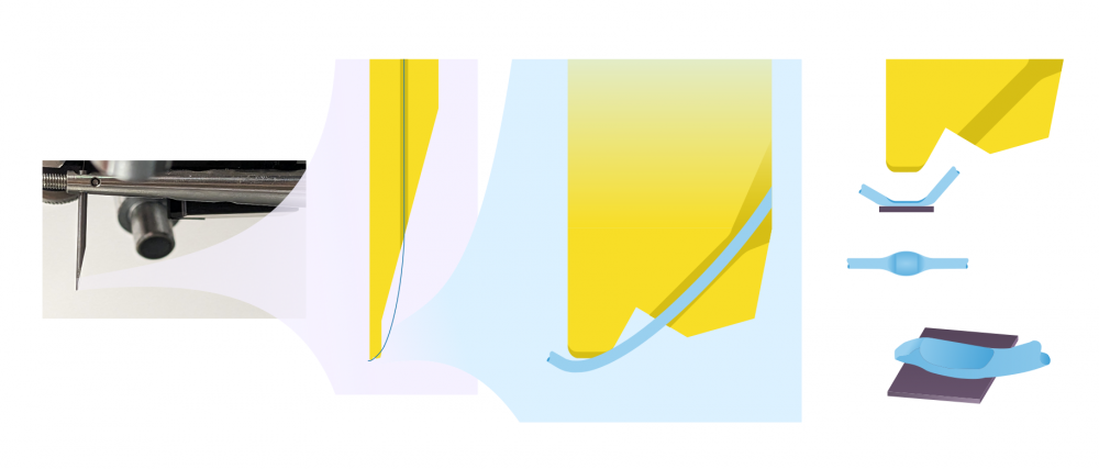
A detailed view of the wirebonder wedge is shown below.
¶ Wires
The most important properties of wire bonding wires are the thickness and the material dependent properties. Modern wire diameters start from around 8 um and can move up to thick wires for packaging batteries. In our lab, we use wire with 25 um diameter, which is small enough to interface with patterned structures.
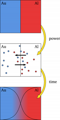
Depending on the material of the die, the choice of wire can change. Typical wire materials are aluminium, gold silver and copper. This variety in wire materials creates a landscape of possible interfaces with the range of thin-film materials that we can sputter and evaporate. The Au-Al (gold wire to aluminium pad)[1] is the most common interface in IC-packaging, but at the Leiden Nanolab, we typically use Al-wire (with 1% Si), and the PCBs to which we bond are typically Au-plated, which means that we operate in the Al-Au interface. Although sounding similar due to its symmetry, the Au-Al and Al-Au interfaces have some key differences, since it is typically the wire material that is the primary diffusant, changing the type of intermetallic compound drastically. In Au-Al, there can form Au5Al2, AuAl2 and Au2Al, resulting in Kirkendall void formation[2] and the "purple plague"[3], which is the main cause of failure.
¶ Bonding Parameters
¶ Ultrasonic Power (P) (typical range: 1-2):
The ultrasonic power applied determines the amount of energy applied to the bond, by varying the amplitude of the ultrasonic vibrations.
Higher power increases interfacial friction and bond strength but can also damage soft metals or delicate structures.
If the bond still doesn't set at powers > 2, you should check if your sample is mounted correctly. For instance, if the sample is resonating with the needle while it's applying the ultrasounds, there is less friction between, and therefore, no bond will be set. Increasing the power will not solve that.
If you keep trying to bond at high powers, there is a chance that you will set a bond between on the wedge itself, resulting in a clogged wedge. This means the wedge needs to be replaced, which means downtime.
¶ Bond Time (T) (typical range: 1-5):
Duration the tool is in contact with the wire while vibrating.
Longer time allows more energy to transfer, but can overheat or deform the bond.__
¶ Bond Force (F) (typical range: 1-2):
The downward pressure from the tool. The bonding force is applied to the wire, while the ultrasonic power is being applied. It consists of a static force which is determined by counterweights in the machine itself and an amount applied by the electromagnetic coil. The latter one is determined by the force dial. The value indicated by the dial is merely used to make a recipe which works for specific applications.
Too little force causes poor bonding; too much can crush pads, crack capping/passivation layers, or thin the wire excessively.
¶ Finding the correct bonding parameters
Finding the right parameters for you process can be a tedious job and requires some work and experience. Please check the logbook if there are any similar samples so that you can use those parameters (P/T/F) as a starting point. Be aware that if you go out of their typical ranges, you are probably not on the right track...
Bond doesn't work. There is nothing on the sample.
There is not enough friction: increase Force or Time.
Bond doesn't work. There is a pancake of wire on my sample.
There is way too much friction. Decrease Time or Power.
Bonds are weak, they break easily.
You might be flattening the wire too much: decrease Force!
Bonds are set, but when moving to the loop height, they still break.
Lower the Loop Height to about the same height as the 1st Search Height. Upon setting the first bond, slowly increase the Loop Height. If the bond still breaks when you do this very carefully, you might want to perform a reverse stepback-manoeuvre to make sure that the tension is not on the bond, but in a kink in the wire.
None of these work?
If changing the Time and Force doesn't work, try changing the Power. If the Power > 2, and it still is not working, the problem lies in your sample, not the wire bonder. Make sure that the sample is mounted rigidly, so that no resonance effects occur. Make sure that the sample is flat, so that the foot of the wedge is optimally touching the sample surface.
¶ Process parameters
¶ Search height
The search height determines the height at which the bond head stops before making the actual bond. This allows for fine positioning of the wedge over the bondpad. The search height should be 75-100 μm above the bondpad surface (~3 times the wire thickness). A different search height can be specified for the first and second bond when there is a height difference between the first and second bondpads. When the first and second bond are in the same plane, both search heights should be equal. (If you want to bond in manual mode it is still important to set the correct search height, this should be done in semi-auto mode.)
Make sure that the search height is above the substrate surface! This prevents the needle from crashing into your sample, potentially destroying it. If you want to play it save, increase the search height to the maximum before putting your sample underneath the needle.
¶ Loop height
After the first bond is made, the wedge is set to the loop height, which is dependent on the bond length needed, whether or not the first and second bond are in the same plane and so on. The value set is an absolute value and does not depend on the search height. This means that when the search height is changed, it is probable that the loop height needs to be adjusted as well.
If you decide to increase the loop height, more wire will be used for your bond. If you accidentally have too much wire, and you want to decrease the loop height, you will see that the wire does not go back in the bonding tool. Use the loop height wisely.
¶ Tail length (typical value: 5):
For wedge bonding, the tail length determines the wire length which is produced after the second bond. Thus, it is also the amount of wire with which the first bond starts.
Because the K&S-4700 is a relatively old system (>20 yrs), this tail is not very reliable anymore. Between every set wire bond, you should check the tail using the microscope! If the tail is not enough, feed the wire manually.
(For ball bonding, it also determines the wire length after the second bond, but this length then is a critical factor in the Electric Flame Off (EFO) process as the amount of wire determines the size of the ball. This means that too little tail produces a too small ball (which can get stuck in the capillary) and too much tail will result in problems when doing the EFO.)
¶ Kink height & reverse (optional)
Normally when the wedge moves to loop height, the first bond has to withstand extra stress because the wire is pulled from it. This can make the bond weaker or even loosen it completely. To avoid this, a kink can be made just after the first bond, before making the loop. This is done by adjusting the kink height and reverse dials.
The first of the two determines to height to which the wedge will rise (and thus the wire length protruding the bond). Adjusting the reverse dial will influence the amount of reverse motion of the table, after the the wedge has risen to kink height. After the table has reversed, the wedge will rise to loop height. This way, when rising to loop height, the kink will be under stress, not the first bond.
¶ Stepback (optional)
The stepback determines the distance the motorized table moves between the first and second bond pads (if they are at a regular distance this is useful). The maximum stepback setting is 6.4 μm. To use the stepback the motor has to be turned on at the right button panel of the machine.
For a short animated video that shows the kink height/reverse and stepback so that a nice bow bond is made, here.
Wikipedia: Gold–aluminium intermetallic. ↩︎
A. D. Smigelskas and E. O. Kirkendall, “Zinc Diffusion in Alpha Brass,” Transactions of AIME, Vol. 171, 1947, pp. 130-142. ↩︎
Horsting, C.W., “Purple Plague and Gold Purity,” 10th Annual Proc. IEEE Reliability Physics Symp., Las Vegas, Nevada, 1972, pp. 155-158. ↩︎